 |
||
|
||
| ||
|
||
|
||
| ||
DDR2 is a new memory standard approved by JEDEC (Joint Electronic Device Engineering Council) that comprises a great number of DIMM, chip, and chipset manufacturers. The standard's eariler versions were published back in March 2003, but it wasn't until January 2004 that it gained the ultimate approval and got the name of DDR 2 SDRAM SPECIFICATION, JESD 79-2, revision A (JESD79-2A). DDR2 is based on a well-known and time-proved DDR (Double Data Rate) technology. We can even say that it begins where the latter ends. In other words, first DDR2's will work at the frequencies that are the limit for this generation of DDR-400 (PC3200 standard, 200-MHz clock frequency), while its further variants will leave the latter even farther behind. The first DDR2 generation is already in production. It is manufactured by such vendors as Samsung, Infineon, Micron, Crucial, Kingston, Corsair, and is represented by DDR2-400 and DDR2-533, that work at 200 and 266 MHz, respectively. The next generation will include DDR2-667 and DDR2-800 modules, although they are not much expected to appear in sale by the end of the year. It should be mentioned that the DDR2 memory itself appeared quite a while ago (we certainly mean memory on graphic cards). However, this variant of DDR2 (called GDDR2) is, in fact, a special type of memory. It is developed specifically for the graphic card market and has some differences from the desktop variant which is the subject of our today's review. Background informationSo, the desktop DDR2-SDRAM is regarded as an evolutionary replacement of the current DDR memory. It functions on the same principle: data are transmitted (on the DIMM level) via a 64-bit bus on both parts of the synchrosignal (ascending front and descending profile), which ensures an effective data transmission speed double to its frequency. Certainly, DDR2 also features a number of innovations that enable to reach much higher frequencies (and hence, higher bandwidth), more capacious chip arrays, and lower energy consumption as well. We'll dwell on the details later, and now we're going to deal with macroscopic facts. DDR2 DIMMs are produced in a new form factor: 240-contact modules that are electrically incompatible with slots for DDR DIMMs (in the number of pins, the distance between them, and the pinout). Thus, the DDR2 standard doesn't imply backward compatibility with DDR. The table below comprises approved specifications of first three DDR2 standards.
We can see that DDR2-400 is marked by the same bandwidth as the current
DDR-400 type.
First DDR2 DIMMs will be shipped in the following variants: 256 MB, 512 MB, 1 GB. However, the standard also enables to build up-to-4-GB modules, though they are not compatible with desktop ones, at least for the moment. And even more capacious modules are expected to appear in the future. DDR2 chips will be made using package of the FBGA (Fine Ball Grid Array) type. This package is more compact than the traditional TSOP-II and ensures higher chip capacity with a smaller size and improved electric and thermal characteristics. Some DDR manufacturers already use this package type, but it is recommended for the JEDEC standard. According to the standard, DDR2 consume 1.8 V (against DDR's 2.5 V). As a result, energy consumption has lowered, which is an essential factor for manufacturers of both notebooks and large workstations or servers, as DIMMs' power dissipation is of great importance there. DDR2 insideThe DDR2 standard introduces a number of major changes into DDR data transmission, that enable to reach higher frequencies at lower energy consumption. Right now, we're going to examine this mechanism in details. Data prefetchThe main difference is that DDR2 enables 4n-prefetch, in contrast to 2n-prefetch realised in DDR. It means, in fact, that at each memory bus cycle, DDR2 transmits 4 (instead of 2) bits of information from logical (internal) memory chip banks into I/O buffers using one data interface line. But then the question is why DDR2-400's effective bandwidth appears to be the same as that of a standard DDR-400 (3.2 GB/s). Why doesn't it double?
To answer this question, we'll have to examine the work of standard DDR-400 memory. In this case, both the memory core and the I/O buffers function at 200 MHz while the effective frequency of the external data bus is 400 MHz due to the DDR technology. As it is 2n-prefetch, 2 bits of information arrive in the I/O buffer from each data interface line at each memory cycle (200 MHz). The buffer multiplexes/demultiplexes (MUX/DEMUX) the data flow. Because DDR SDRAM chip's logic banks have data buses twice as wide as the distance between the read latches and the external interface, the data buffer includes a 2-1 multiplexer.
Generally speaking, because memory chips, in contrast to modules, can have a variable data bus width (normally x4/x8/x16/x32), the use of such MUX / DEMUX (2-1) scheme realised in DDR means that an X-wide inner data flow with a Y transmission frequency transforms into an X/2-wide external flow with a 2Y frequency.
This is called a peak bandwidth balance.  Now let's look at a DDR2 SDRAM chip, equifrequent and "equiwide" regarding DDR-400 DIMM. First of all, the width as well as the effective frequency of the external data bus remain the same, 1 bit/line and 400 MHz, respectively. This is, in fact, enough to answer our question why DDR2 and DDR equifrequent DIMMs have one and the same theoretical bandwidth. Then it is obvious that a 4n-prefetch 2-1 multiplexer used in DDR SDRAM is not suitable for DDR2 SDRAM. Instead, a more complex scheme with an additional transformation step is needed, such as a 4-1 multiplexer. That means that the core output has become four times wider than the external chip interface and four times lower in the functioning frequency. Thus, analogically to the example above, the MUX/DEMUX 4-1 scheme generally transforms an X-wide internal data flow with a Y transmission frequency into an X/4-wide external flow with a 4Y frequency.  In this case, the core of the memory chips is synchronised at a frequency twice as low as the external one (100 MHz) while DDR synchronises the internal and the external data flows at the same frequency (200 MHz). Therefore, such approach enables to increase the percentage of chip yield and lower energy consumption. By the way, it also explains why the DDR2 standard implies the existence of DIMMs with a 800-MHz effective frequency (which is twice as high as the current DDR generation has). This frequency can be reached right now if we have DDR-400 memory chips working at a 200-MHz core frequency and execute a 4n-prefetch data selection bas ing on the scheme above. Thus, DDR2 turns from the extensive way of memory chip development, which implies a further frequency increase and is a rather serious obstacle to the mass production of stable-working DIMMs. Instead, it takes on an intensive way based on the extension of the inner data bus. (The solution is inevitable and obligatory if we use more complex multiplexing.) We dare to suppose that the future may see the DDR4 type that will have 8n-prefetch and a 8-1 multiplexer, and will work at the frequency 4 times lower than the I/O buffer frequency :). Actually, the approach is nothing new, we have seen a similar thing in Rambus DRAM chips. But it will also have a reverse side to it, namely — an increasing complexity of I/O buffer MUX/DEMUX, which will certainly affect memory latency. On-die terminationThe DDR2 standard also comprises other modifications which improve various memory parameters, including electric ones. For example, on-die signal termination is based on the following principle: in order to reduce electric noise (caused by the signal reflection from the end of the line), memory bus resistors are placed not on the motherboard (as was the case with previous memory generations) but inside the chips. The resistors are deactivated when the chip is working and are activated as soon as the chip slips into a standby state. Because the signal is now terminated much closer to its source, electric noise can be eliminated inside the memory chip during data transmission. And speaking about on-die termination, we can't but mention the module's heat emission which the new DDR2 standard is designed to lower in the first place. Indeed, such signal termination creates considerable static currents inside the memory chips and results in their heating. In general, however, the memory subsystem will not consume more power because of this as the heat is just dissipated elsewhere now. The problem lies in the possibility to increase the functioning frequency of such devices. Probably, this is why the first DDR2 generation is represented by DDR2-400 and DDR2-533 modules, and not by DDR2-800 ones, as the former two have an acceptable heat emission rate inside the chips. Additional latency
Additive latency also known as CAS latency is another modification introduced into the DDR2 standard. It is designed to minimise instruction scheduler idles during data transmission to/from the memory. To illustrate this, let's take data read from a DDR2 device in the following conditions: Bank Interleave, additive latency = 0 (which is equal to read from a standard DDR memory).
 The first stage features the bank opening with the help of the ACTIVATE instruction and the provision of the first component of the address (line address), which selects and activates the necessary bank and the line in its array. During the next stage, the information is transmitted to the internal data bus and then goes to the sense amplifier. When an amplified noise level reaches the necessary value (after the latency time between line address and column identification, tRCD (RAS-to-CAS Delay) has elapsed), a READ with Auto-Precharge (RD_AP) instruction can be sent for execution along with the address column, in order to select a precise address of the data that are to be read from the sense amplifier. After the read instruction comes the execution of CAS latency (tCL), during which the data selected from the sense amplifier are syncronised and transmitted to the chip's external pins. It can create a situation where the next instruction (ACTIVATE) can't be sent for execution as other instructions hasn't yet been executed. Thus, if we take our example, the activation of the second bank has to be put off by one clock, as the execution of RD_AP from bank 0 is still in process. In the end, it leads to a break in the succession of data arrival via the external bus, which reduces real memory bandwidth.
To eliminate it and increase the efficiency of the instruction scheduler, the notion of additive latency (tAL) is introduced into
DDR2. When
tAL is not equal to zero, the memory device monitors READ (RD_AP) and WRITE (WR_AP) instructions, but postpones their execution by the time equal to the additive latency value. The picture below shows the difference in DDR2 chip's behaviour caused by two different tAL values.
 The picture above describes DDR2 chip functioning at tAL = 0, which is equivalent to a standard DDR device; the one below illustrates the case when tAL = tRCD - 1, which is typical of DDR2. Given this configuration, ACTIVATE and READ instructions can arrive for execution one by one. The actual realisation of the READ instruction will be postponed by the additive latency value, that is, it will be executed at the same moment as shown in the diagram above.  This picture illustrates data read from DDR2 chip if tRCD = 4 clocks, which makes tAL = 3 clocks. In this case, due to the additive latency, ACTIVATE/RD_AP instructions will be executed in a row, enabling a continuous data arrival and a maximised real memory bandwidth. CAS latencyAs we have seen above, DDR2 works at higher external bus frequency than DDR SDRAM. However, the new standard implies no substantial changes in the chip production technology, therefore, static latencies on the DRAM device level must remain more or less constant. 15ns is a typical internal latency value for DDR-type DRAM devices. It equals 2 clocks for DDR-266 (7.5ns cycle time) and 4 clocks for DDR2-533 (3.75ns cycle time).  As memory frequencies increase, the number of supported CAS latency values should be multiplied (towards higher values). The table below comprises CAS latency values specified by the DDR2 standard. They include integers from 3 to 5 clocks; fractional latencies (divisible by 0.5) can't be used in the new standard.  DRAM device latencies are identified as the cycle time (tCK) multiplied by the selected CAS latency value (tCL). Typical latency values for DDR2 devices can be found in the 12-20ns interval basing on which the CAS latency value is selected. The use of higher latency values is inexpedient in terms of memory subsystem performance, while lower ones shouldn't be used as they prevent the memory device from stable work. Write latency
The DDR2 standard also introduces some changes into the write latency (the WRITE instruction).
The picture below shows the difference in DDR and DDR2 behaviour.
 DDR SDRAM has write latency equal to 1 clock, which means a DRAM device starts to capture information via the data bus one clock (on average) after the WRITE instruction arrives. However, as DDR2 devices have an increased speed, this period turns out to be too short for the DRAM device (namely, its I/O buffer) to prepare for data capturing. Thus, the DDR2 standard identifies write latency as CAS latency minus 1 clock (tWL = tCL - 1). The fact that WRITE latency depends on CAS latency enables to reach higher frequencies and simplifies read/write synchronisation (Read-to-Write timings setting). Turn after write The write-into-SDRAM procedure is analogical to the read operation, the only difference lying in the additive interval tWR which characterises the interface's post-operational turn-around period (it is usually a 2-clock latency between data arrival onto the bus and the innitiation of the new cycle). This interval measured from the moment the operation ends to the moment the regeneration stage begins (Auto Precharge), enables the interface to turn around after the write operation and guarantees its correct execution. Noteworthy, the DDR2 standard brings no changes into the turn-after-write period. Thus, DDR2 device latencies can generally be referred to the few characteristics in which the new standard proves inferior to DDR. Therefore, it is obvious that the use of an equifrequent DDR2 will hardly bring any performance gain compared to DDR. But as usual, only tests can tell what it's like in reality. RightMark Memory Analyzer test results
Now we've come to the results that we received using RightMark Memory Analyzer benchmark version 3.1. It will be recalled that the main advantages of this test consist in rich functionality, open methodology (anyone can see the test in the form of the source code) and a thoroughly worked-out documentation. Testbed configurations and softwareTestbed 1
Testbed 2
Software
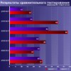
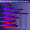
Maximal real memory bandwidth
We measured maximal real memory bandwidth using the Memory Bandwidth subtest, presets Maximal RAM Bandwidth,
Software Prefetch, MMX/SSE/SSE2.
The very names of the presets indicate a standard optimisation of memory read operations (Software Prefetch). Its essence boils down to the prefetch of the data that will further be taken from RAM into L2 CPU cache. The Non-Temporal Store method that enables to avoid cache waste is used for memory write optimisation. We got nearly identical results, using MMX, SSE, and SSE2 registers. To illustrate this, here is a graph received on Prescott/DDR2 using SSE2.  Prescott/DDR2, maximal real BW Noteworthy, there are no great qualitative differences between DDR and DDR2
on equifrequent Prescotts in this test. Even more interestingly, quantitative
BW characteristics of DDR-400 and DDR2-533 are very close too (see
the table) despite the fact that DDR2-533 memory has maximal theoretical
BW of 8.6 GB/s (in the dual-channel mode). However, it comes as no
big surprise, as the CPU still has a 800-MHz Quad-Pumped Bus with
a 6.4GB/s bandwidth which prove to be the limiting factor.
As for the efficiency of write operations compared to read ones, it remains the same. However, it is natural too, as in this case, write BW limit (2/3 of read BW) is clearly formed by peculiarities of Prescott CPU microarchitecture. Memory latencyFirst of all, we'll tell you how and why we measured true memory latency, as it is not at all a trivial task to measure it on Pentium 4 platforms. The CPUs of this family (especially the new Prescott core) are marked by a quite advanced asynchronous hardware data prefetch which hampers an objective measurement of the feature in question. Evidently, forward/backward memory read methods are not suitable for measuring its latency in this case, as the Hardware Prefetch algorithm will work at its maximal efficiency hiding latencies. Random modes are much better, although a truly random memory read has a serious drawback. The thing is, such measurement is performed at nearly 100-percent D-TLB miss which creates additional latencies (we wrote about it). Thus, the only possible variant within methods realised in RMMA is pseudo-random memory read mode where each following line is loaded in a linear way (annihilating D-TLB misses) while memory read within the page is truly random. Still, our previous
measurements show that even this method lowers latency values
quite significantly. In our opinion, it is connected with another
peculiarity of Pentium 4 CPUs, namely — that they can capture
two 64-bit lines from the memory into L2 cache at each access. To
illustrate this, here is a graph that shows curves reflecting dependence
of two accesses to the same memory line on the offset of the second
line element from the first one. The results were received on a Prescott/DDR2
platform using the D-Cache Arrival test, preset L2
D-Cache Line Size Determination.  Prescott/DDR2, data arrival via L2-RAM bus As we can see, access to the second element entails no additive latencies up to 60 bytes (which fits the true size of L2 cache line, 64 bytes). The area between 64 and 124 bytes corresponds to data read from the next memory line. Considering the fact that latency values do not increase dramatically in this area, we can state that the next memory line is really fetched into L2 CPU cache right after the requested one. So, what practical conclusion can we draw from it all? If we want to "deceive" this peculiarity of the Hardware Prefetch algorithm, that works in all memory read cases, we only have to read the chain at steps equal to the so-called effective L2 cache line size, which is 128 bytes in our case.
Now it's time we go straight to the results of latency measurements. Here are L2-RAM bus offload graphs, received on a Prescott/DDR2 platform.
 Prescott/DDR2, memory latency, line size: 64 bytes  Prescott/DDR2, memory latency, line size: 128 bytes
As was the case with real BW tests, latency curves received on the other platform (Prescott/DDR) look the same in terms of qualitative characteristics. But quantitative ones have the following differences:
*latency with no L2-RAM bus offload As you can see, DDR2-533 has higher latency than DDR-400. However, it shouldn't come as a surprise after we described the theoretical basis of the new DDR2 standard. The difference between DDR and DDR2 latencies is practically invisible (3 ns) at a standard 64-byte memory read when the hardware prefetcher is active. But it becomes much more obvious in the case of the dual-line 128-byte read. Here, minimal DDR2 latency (55.0 ns) is equal to maximal DDR latency. If we compare minimal and maximal latencies within their categories, the difference is about 7 to 9 ns (15-16 percent). At the same time, meduim latencies received when there is no L2-RAM bus offload are surprisingly similar, both at a 64-byte read (with data prefetch) and at a 128-byte one (without data prefetch). ConclusionThe main conclusion we can make basing on the results of the first comparative testing of DDR and DDR2 is that the time of the latter hasn't yet come. There is no point in increasing theoretical BW by means of raising the external memory bus frequency as the current CPU generation still has buses functioning at 800 MHz, which limits real memory BW at 6.4 GB/s. And that, in turn, means that it's too early to install new DIMMs that have higher theoretical BW because the current DDR-400 memory works all right in the dual-channel mode and besides, has smaller latency. Speaking of which, an increase in the external memory bus frequency leads inevitably to the introduction of additive latencies, and our test results prove that. Thus, we can say that it won't be appropriate to use DDR2 at least until new CPUs appear that will have 1066 MHz and higher bus frequencies. Only this will enable to overcome the limit imposed by CPU bus speed on real memory bandwidth.
Dmitri Besedin (dmitri_b@ixbt.com)
24.06.2004
Write a comment below. No registration needed!
|
Platform · Video · Multimedia · Mobile · Other || About us & Privacy policy · Twitter · Facebook Copyright © Byrds Research & Publishing, Ltd., 1997–2011. All rights reserved. | ||||||||||||||||||||||||||||||||||||||||||||||||||||||||||||||||||||||||||||||||||||||||||||||||